AAM Various Engines
| 1st Run |
Brand | Name | Model | HP | Weight | Built | |
| 1918 | Liberty | L-12 | 420 | 845 | 20,748 | 1924 Douglas World Cruiser | |
| 1927 | Warner | Super Scarab | SS-50 | 145 | 303 | Used on: Fairchild 24 | |
| 1928 | Szekely | SR-3 | 45 | 135 | |||
| 1930 | Allison | V-1710 | 1,500 | 1,395 | 69,305 | TMA-76-18 ASM 92-21-15 | |
| 1930 | Allison | V-1710 | 1,500 | 1,395 | P-40 | ||
| 1930 | Franklin | 4AC | 175 | 376 | |||
| 1930 | LeBlond | 90 | 90 | ||||
| 1931 | Aeronca | E-113 | 36 | 118 | ≈1,800+ | ||
| 1935 | Ranger | L-440 | 175 | 376 | Used in Grumman Widgeon | ||
| 1943 | McCulloch | 0-100-1 | 72 | 77 | ≈70,000+ | Used in Radioplane OQ-19D | |
| 1947 | Fairchild | J-44-R-20 | 345 | Turbojet | |||
| Signal Corps | PE-77-D | Small 1 cylinder 115V DC generator | |||||
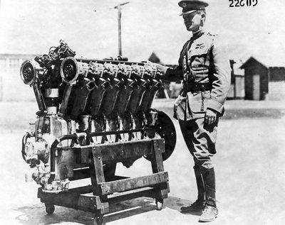
Liberty L-12
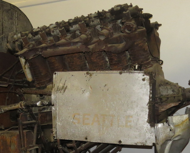
The United States declared war on Germany on April 6, 1917. The Aircraft Production Board, then headed up by Howard E. Coffin of the Hudson Motor Car Co. and his assistant Edward A. Deeds, a major stockholder in Delco, set the basic parameters for what would come to be known as the Liberty. The new engine would be lighter and slightly more powerful than the Rolls-Royce Eagle. Modular construction, employing common cylinder and valve components, would slash development time and permit the engine to be used on all types of airplanes from trainers to heavy bombers. And all this would be accomplished within the strictures of a conservative design philosophy.
The first of many expedients was to telescope layout into a two-day (some say five-day) marathon at the New Willard hotel in Washington, DC that begun in the afternoon of May 31, 1917. At General Pershing's request, the L-8 was put on hold in favor of a 12-cylinder L-12 that would be more powerful than existing Allied engines. The first of these was tested in August, 1918.
The 45º cylinder angle raised questions about torsional vibration. Robert J. Raymond demonstrated that the L-12 crankshaft underwent severe torque peaks at 1,333 rpm, 1,714 rpm and 2,000 rpm. Any of these inputs could result in failure. Raymond quotes two studies dating from the 1930s that indicate the presence of torsional vibration at certain operating speeds. One of these studies described Liberty crankshaft breakage as "epidemic."
The Liberty had other faults. C. Fayette Taylor, who was in a position to know, reported that half of the early production engines could not pass the 50-hr acceptance test. Burnt exhaust valves and, as has been pointed out, accessory-gear failures were common on all versions.
TBO, or time between overhauls, is the primary measure of durability. By 1926 Navy L-12s were averaging 75 hours between overhauls. Newer air-cooled engines had TBOs of 300 hours
Once the war ended, the problem became what to do with the engines, for which few airframes were available. Some were donated to the Air Mail Service and vocational schools, and others were sold as surplus for pennies on the dollar. Rum runners found that 400 hp gave them an advantage over Coast Guard cutters. Still, by 1924, 11,810 L-12s remained in inventory, enough to satisfy military needs for 26 years.
Although the Liberty had very limited application for military aircraft, the overhang made it difficult to justify acquisition of newer and more expensive power plants.
Attempts to convince commercial operators to adopt the engine on economic grounds failed. It vibrated, weighed more than it should, and had a reputation for unreliability. Army mechanics did their part by foregoing overhauls. When an L-12 needed work, they replaced it with a new one. That practice continued until 1929.
Used on the 1924 Douglas World Cruiser
Liberty L-12
| General Characteristics | ||
|---|---|---|
| First Run: | 1918 | |
| Number Built: | 20,748 | |
| Type: | 12-cylinder liquid-cooled Vee piston engine | |
| Bore: | 5 in | 127 mm |
| Stroke: | 7 in | 178 mm |
| Displacement: | 1,649 cu in | 27.03 L |
| Length: | 67.375 in | 1,711 mm |
| Width: | 27 in | 685 mm |
| Height: | 41.5 in | 1,054 mm |
| Dry weight: | 845 lb | 383.3 kg |
| Components | ||
| Valvetrain: | 1 inlet and 1 exhaust valve per cylinder | |
| Fuel system: | Two duplex Zenith Carburetors | |
| Fuel type: | Gasoline | |
| Oil system: | Forced feed, rotary gear pressure and scavenge pumps, wet sump | |
| Cooling system: | Water-cooled | |
| Performance | ||
| Power output: | 449 hp at 2,000 rpm (takeoff) | 334 kW |
| Specific Power: | 0.27 hp/cu in | 12.4 kW/L |
| Compression ratio: | 5:1 | |
| Specific fuel consumption: | 0.565 pt/hp/hour ≈28 gal/hour |
0.43 l/kW/hour |
| Oil consumption: | 0.0199 pt/hp/hour ≈1 gal/hour |
0.0152 l/kW/hour |
| Power-to-weight ratio: | 0.53 hp/lb | 0.87 kW/kg |
1927 Warner Scarab
Used on: Fairchild 24
The Warner Scarab is an American seven-cylinder radial aircraft engine, that was manufactured by the Warner Aircraft Corporation of Detroit, Michigan in 1928 through to the early 1940s.
Super Scarab SS-50/50A - Increased cylinder bore to 4.625 inches to develop 145 hp (108 kW) at 2,050 rpm from 499 cu in (8 l) with a dry weight of 303 lb (137 kg).
Warner Super Scarab SS-50
| General Characteristics | ||
|---|---|---|
| First Run: | 1927 | |
| Number Built: | ||
| Type: | Seven-cylinder air-cooled radial piston engine | |
| Bore: | 4.625 in | |
| Stroke: | 4.25 in | 108 mm |
| Displacement: | 499 cu in | 8 L |
| Length: | 14 in | 35.5 cm |
| Diameter: | 36.5 in | 93 cm |
| Dry weight: | 303 lb | 137 kg |
| Components | ||
| Valvetrain: | 1 inlet and 1 exhaust valve per cylinder | |
| Fuel system: | 2 Stromberg carburetors | |
| Fuel type: | 67 octane gasoline | |
| Oil system: | Dry sump | |
| Cooling system: | Air-cooled | |
| Performance | ||
| Power output: | 145 hp @ 2,050 rpm | 108 kW |
| Compression ratio: | 5.15:1 | |
| Power-to-weight ratio: | 0.43 hp/lb | |
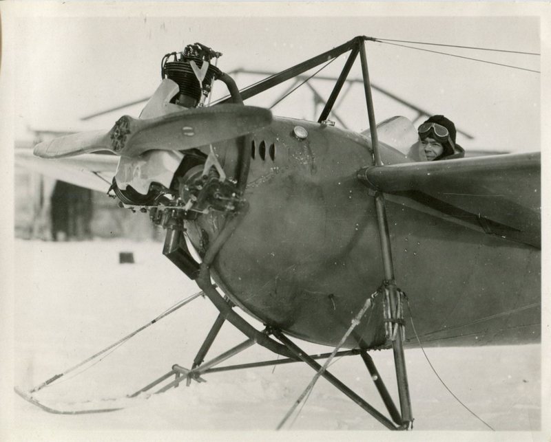
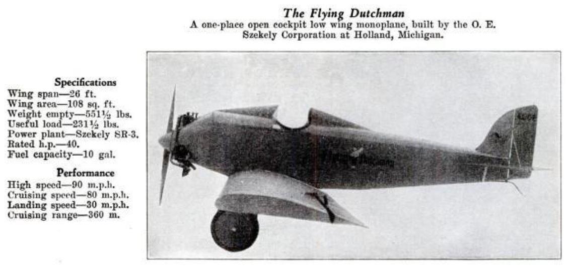
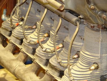
Szekely Engine
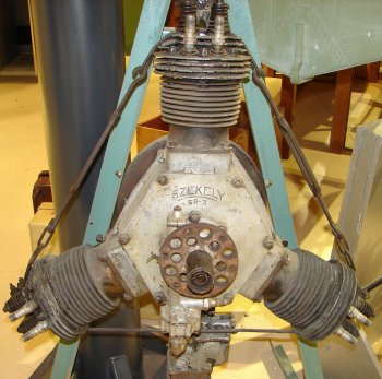
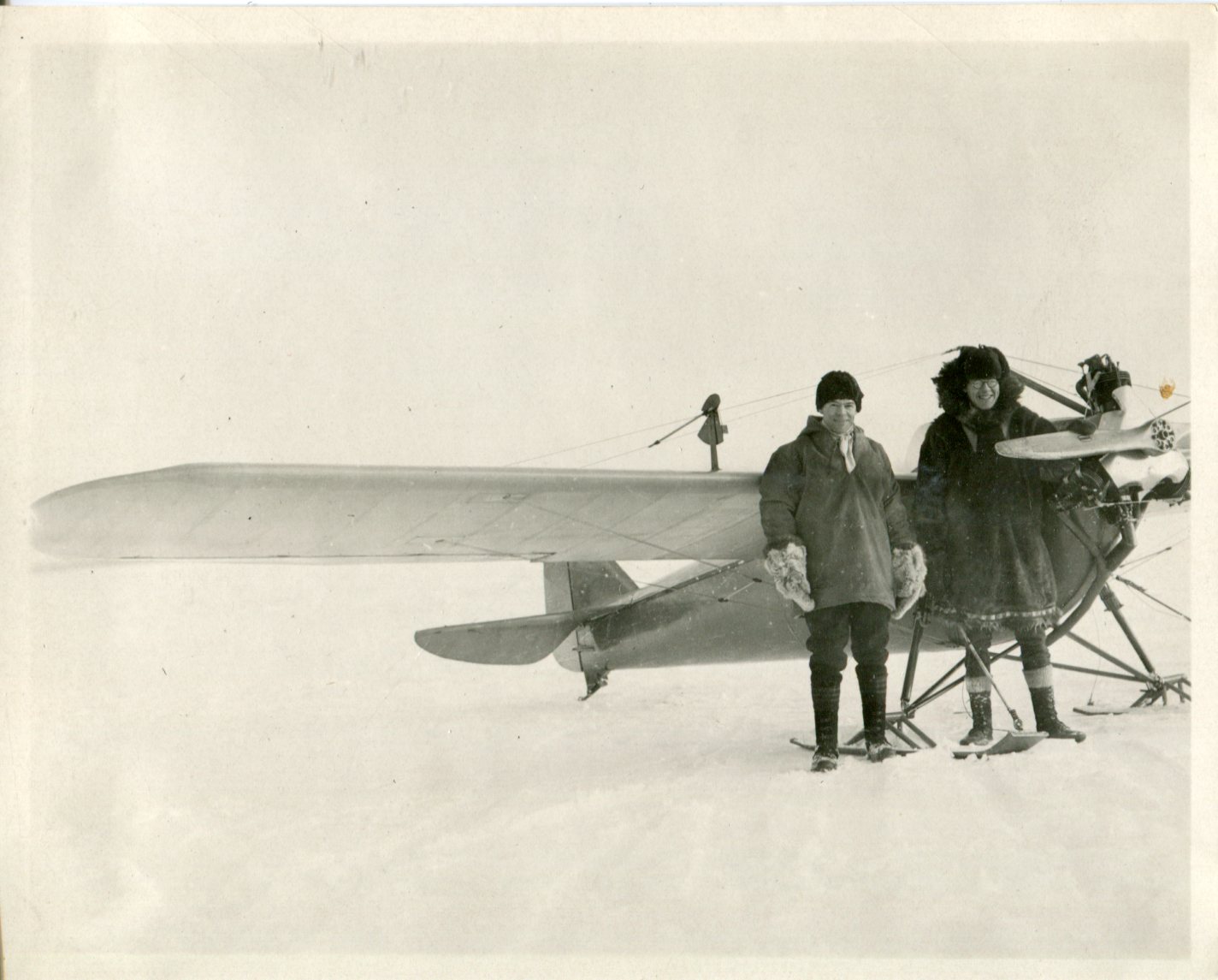
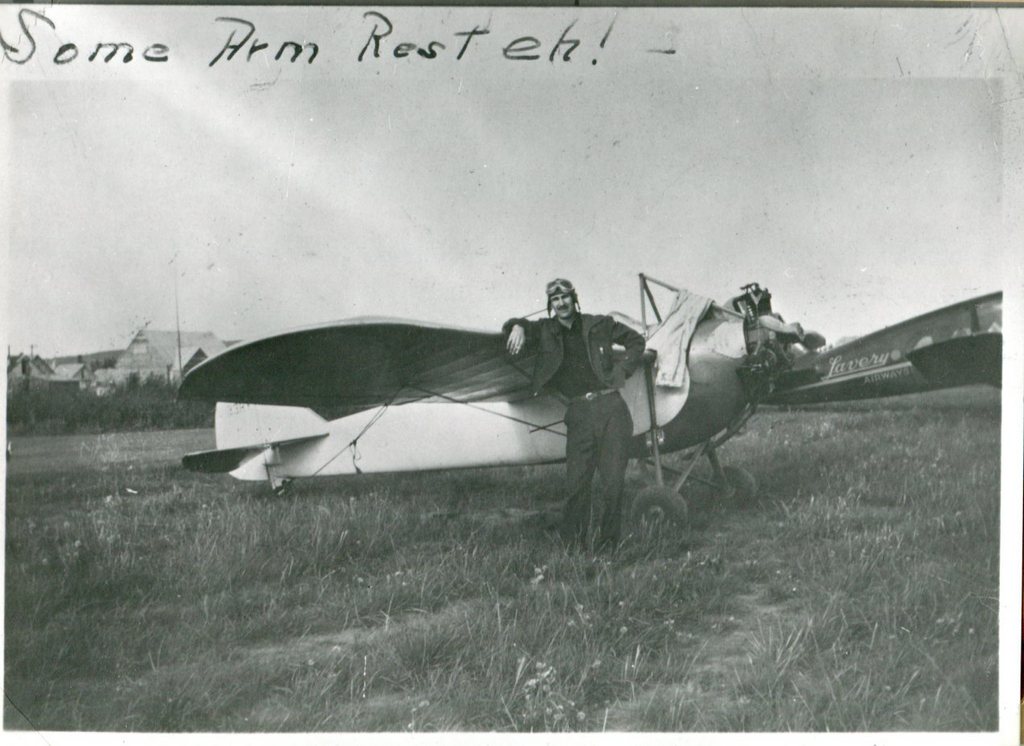
Three cylinder radial engine built in Holland, Michigan. The O.E. Szekely Corporation of Holland was founded in 1928 to build light aircraft and engines. They were used to power small aircraft such as the Rearwin Junior, Taylor H-2 and American Eagle Eaglet. Often criticized for reliability issues and design flaws many were replaced with better engines in their original airframes. Few examples still exist.
The cylinders had a tendency to break off in operation and the cable around them was an attempt to prevent that from happening. There is no record of how successful that was.
hollandsentinel.com
Szekely-aircraft-topic-of-Vintage-Car-Club
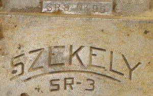
Szekely SR-3
| First Run: | 1928 | |
|---|---|---|
| Number Built: | ||
| Bore: | 4 1/8 in | 105 mm |
| Stroke: | 4 3/4 in | 121 mm |
| Displacement: | 191 cu in | 3.13 L |
| Length: | 23 in | 584 mm |
| Diameter: | 36 in | 914 mm |
| Dry Weight: | 135 lbs | 61 kg |
| Power: | 45 hp at 1750 rpm | 34 kw |
Allison V-1710 12 CYLINDER -60 DEGREE VEE
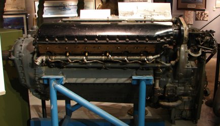
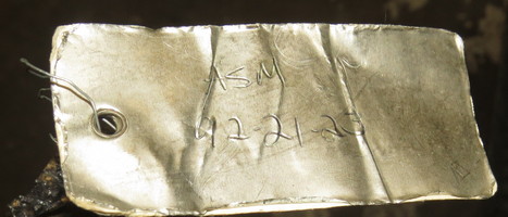
Object ID: TMA-76-18 ASM 92-21-15
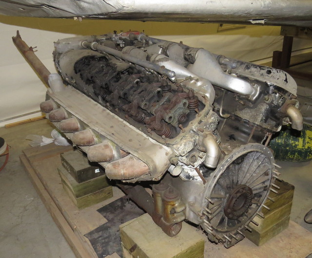
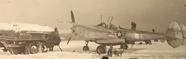
Allison engines were built first for the Bell Aircobra during WWII. Used in Curtis P-40s in the Aleutians.
Allison V-1710-F30R / -111
| General Characteristics | ||
|---|---|---|
| First Run: | 1930 | |
| Number Built: | 69,305 | |
| Type: | 60⚬ V-12 supercharged four-stroke liquid-cooled piston aircraft engine. | |
| Bore: | 5.5 in | 140 mm |
| Stroke: | 6 in | 152 mm |
| Displacement: | 1,710 cu in | 28.02 l |
| Length: | 86 in | 2,184 mm |
| Width: | 29.3 in | 744 mm |
| Height: | 37.6 in | 955 mm |
| Dry weight: | 1,395 lb | 633 kg |
| Frontal Area: | 6.1 sq ft | 0.6 m2 |
| Components | ||
| Valvetrain: | Two inlet and two exhaust valves per cylinder with sodium-cooled exhaust valves, operated by a single gear-driven overhead camshaft per bank of cylinders | |
| Supercharger: | Centrifugal-type, single-stage, 8.1:1 gear ratio, 15-vane impeller, 10.25 in (260 mm) diameter and a General Electric turbo-supercharger with intercooler | |
| Fuel system: | 1 x Stromberg PD-12K8 2-barrel injection downdraught carburetor with automatic mixture control | |
| Fuel type: | 100/130 octane gasoline | |
| Oil system: | Pressure fed at 60–70 psi (414–483 kPa), dry sump with one pressure and two scavenge pumps. | |
| Cooling system: | Liquid-cooled with a mixture of 70% water and 30% ethylene glycol, pressurized. | |
| Reduction gear: | Spur reduction gear, 0.5:1 ratio, right hand tractor (V-1710-F30L / -113 is the same engine with LH rotation) | |
| Starter: | Jack & Heinz JH-5L electric inertia starter | |
| Ignition: | 1 x R.B. Bendix-Scintilla DFLN-5 dual magneto, 2 x 12 point distributors, 2 x spark plugs per cylinder fed by a shielded ignition harness. | |
| Performance | ||
| Power output: | ||
| Take-off: | 1,500 hp at 3,000 rpm and 56.5 inHg manifold pressure | 1,119 kW at 190 kPa |
| Military: | 1,500 hp at 3,000 rpm at 30,000 ft | 1,119 kW at 3,000 rpm at 9,144 m |
| Normal: | 1,100 hp at 2,600 rpm at 30,000 ft | 820 kW at 2,600 rpm at 9,144 m |
| Cruising: | 800 hp at 2,300 rpm at 30,000 ft | 597 kW at 2,300 rpm at 9,144 m |
| Specific Power: | 0.88 hp/cu in | 39.3 kW/L |
| Compression ratio: | 6.65:1 | |
| Oil consumption: | 0.025 lb/hp/hr | 0.01475 kg/kW/hr |
| Power-to-weight ratio: | 1.05 hp/lb | 1.76 kW/kg |
Franklin 4AC-199-E3
The Franklin 4 (US military designations O-150, O-170, O-175, and O-200) was a series of air-cooled aircraft engines of flat-4 configuration produced in the 1930s and 1940s.
4-cylinder air-cooled horizontally opposed aircraft piston engine
Franklin 4AC-199-E3
| First Run: | 1930 | |
|---|---|---|
| Number Built: | ||
| Bore: | 4 1/8 in | 105 mm |
| Stroke: | 5 1/2 in | 139 mm |
| Displacement: | 441 cu in | 7.2 L |
| Length: | 53.156 in | 1.351 m |
| Width: | 21.954 in | 0.549 m |
| Height: | 33.50 in | 0.854 m |
| Dry Weight: | 376 lbs | 170.7 kg |
| Power: | 175 hp at 2,450 rpm | |
| Compression Ratio: | 6:1 | |
| Fuel: | 65 octane | |
LeBlond 90
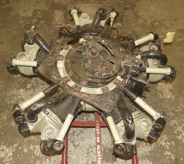
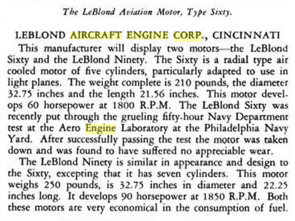
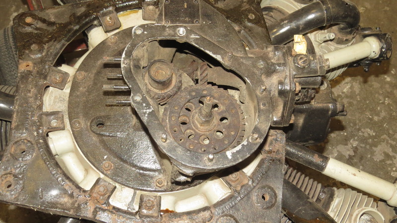
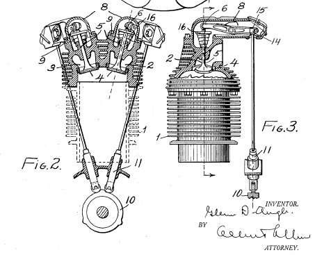
The LeBlond 90 is a 5-cylinder air-cooled radial aircraft piston engine produced in the 1930s.
LeBlond 90
| First Run: | 1930 | |
|---|---|---|
| Number Built: | ||
| Displacement: | 266 cu in | 4.4 L |
| Power: | 90 hp | 68 kw |
If the airplane is flown consistently in temperatures below 20°F or -6°C, it will be found very desirable to cover the oil lines and oil tank with some form of asbestos or similar insulating material. A method of covering the tank is to mix powdered asbestos with water and cover the tank to a depth of about ¼ inch of this material. After allowing the asbestos to dry the tank should then be covered with canvas or other wind-tight material to keep the asbestos in place, and then shellac the canvas.
20-Hour Check
1. Check compression.
2. Check engine support nuts for tightness.
3. Drain the oil tank and refill with clean aero or first-grade automobile oil. (90 h.p. engines require 8 quarts).
4. Clean the fuel strainer and check fuel connections to engine.
5. Examine the condition of the magneto coupling discs.
6. Check magneto breaker gap (either Bendix or Scintilla) to .012” and see that the points are clean. If necessary to change timing, engine should be retimed as follows: Propeller keyway is on the same side of crankshaft as the crank. Line up keyway with the top (#1) cylinder on compression stroke. Then back propeller 30° and magneto points should break at that place. If points do not break, loosen nuts (3 on each magneto) on magneto disc and slip each magneto drive until they do break. Tighten one nut, check, and tighten other two nuts.
7. Lubricate the magneto according to the magneto manufacturer’s instructions. (2 drops every 50 hours.)
8. Lubricate all visible engine controls where there is friction in operation, and check for proper operation.
9. Check the tappet clearances with the engine cold and reset both the exhaust and intake clearance to .010 inches. Reset the tappets before removing the push rods from the rocker boxes.
10. Remove the valve push rods and cover tubes, check the straightness of the rods and the condition of the upper and lower ball ends and push rod sockets, keeping push rods in order so they are sure to be returned to the same position in the same rocker boxes. Lubricate the valve push rods by dipping both ends of the rod in Texaco Marfak No. 2 lubricant. Replace valve push rods and cover tubes.
11. After the reassembly of the valve push rods, etc., lubricate the rocker boxes as follows:
- a. Use Texaco Marfak No. 2 grease in a Zerke or similar pressure grease gun and lubricate that part of the rocker box which has a pressure gun fitting with ten strokes of the Zerke gun after air has been cleared from the gun and grease is flowing.
- b. Use Texaco Marfak No. 2 lubricant in any clean grease gun (pressure or non-pressure) and after removing the ¾ inch metal disc in the top front of each rocker box, fill with Marfak No. 2.
12. Inspect propeller for nicks, dents, loose tips and track. Check propeller hub nut for tightness and safety and the long hub bolts in the propeller for a tight drive fit in the propeller holes. Bolts should be soaped when driven.
13. Wash down motor and motor cowling thoroughly.
14. Replace all engine parts, connections, and wiring that show evidence of wear.
The following items are work which is addition to that included in a 20-hour check, and may be done if a more complete check is desired.
1. Wash out oil tank and lines.
2. Remove rocker boxes and examine valve mechanism, correcting any conditions of wear that may be observed.
3. Remove spark plugs, clean, reset the gap, and test under pressure. Necessary wrenches consist of: Either 1” 12 point socket for Champion plugs, or 11/16” 12 point socket for mica plugs, out from 3” length to 2-1/2” length.
4. Remove and recondition the oil pump, clean screens and replace. (After first 40 hours, thereafter each 100 hours operation on motors before #1299.)
5. Carburetor disassembly and inspection.
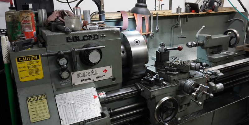
2018-02-27 LeBlond Lathe at AK Airframes in Birchwood
Aeronca E-113
The E-113 was a small flat-twin piston engine developed by Aeronca for use in some of their light aircraft. It was an overhead valve development of the flathead configuration E-107.
Certificated in April 1931, the Aeronca E-113 was an outgrowth of the Wright-Morehouse engine and was designed again for light aircraft. Considered highly reliable, it was the most powerful two-cylinder engine of its time. The E-113 first powered the Aeronca C-1 Cadet aircraft in 1931. It was also used in the Aeronca C-2 and C-3 aircraft. The C-3 was widely used for student instruction in the 1930s.
Originally fitted with a single ignition system, this was uprated to dual ignition when changes in FAA regulations made this mandatory in 1939. By that time, however, both the engine and the aircraft that it powered were facing obsolescence. Altogether, some 1,800 examples were built. Following an incident in October 2015 where the propeller detached from an Aeronca C3 in 2015, the Light Aircraft Association has issued an advisory that all aircraft fitted with these engines have the crankshaft attachment inspected prior to flying again. This issue has been recognised since 1939.
The Aeronatica Corp of America, founded in November of 1928, built the first light aircraft for the General Aviation market. Their C-2 and C-3 aircraft were very popular during the depression because of the low purchase price and low cost of operations.
At the time, there was on really reliable small aircraft engines so the Aeronatica Corporation, the name was change to Aeronca in 1941, designed and built their own. The first one, the E107 was rated at 26 horse power, only a small number was built. The E113 followed and was rated at 36 horse power.
Production ended in 1938, primarily because better, more reliable and higher horsepower engines had become available. You came only do so much to raise the horse power of a 2 cylinder engine to, and the CAA had mandated dual ignition for all aviation engines. Aeronca designed a dual ignition system for the E113 but it proved to be unreliable.
Aeronca E-113
| First Run: | 1931 | |
|---|---|---|
| Number Built: | ≈1,800 | |
| Bore: | 4.25 in | 107.95 mm |
| Stroke: | 4 in | 101.6 mm |
| Displacement: | 113.49 cu in | 1.86 L |
| Dry Weight: | 118 lbs | 54 kg |
| Power: | 36-40 hp at 2,400-2,520 rpm | 26.9-29.8 kW |
| Compression Ratio: | 5.1:1 | |
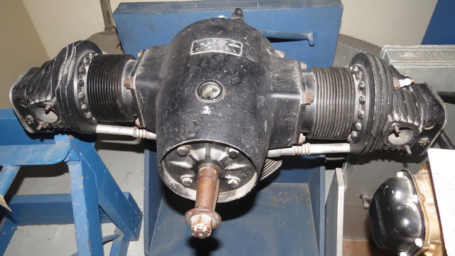
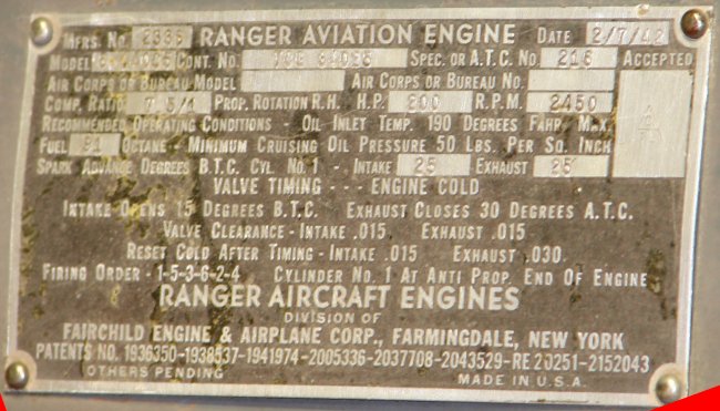
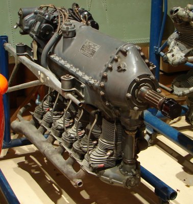
Ranger Engine Model 6-440C5
- Built 2/7/42
- 200 hp with 7.5:1 compression ratio
- 6 cylinder inline inverted air-cooled
- Used in Grumman Widgeon, Fairchild PT-19 and PT-26.
- ASM 92-21-9
airandspace.si.edu - Ranger L-440
Fairchild entered the aircraft engine business in 1925 with the formation of the Fairchild-Caminez engine corporation of Farmingdale, New York.
The L-440-1 completed its 150-hour military type test in June 1939.
The Ranger L-440 (company designation 6-440C) are six-cylinder inline inverted air-cooled aero-engines produced by the Ranger Aircraft Engine Division of the Fairchild Engine and Airplane Corporation of Farmingdale, New York, United States. The engine was mainly produced for Fairchild's family of training aircraft in the mid-1930s.
The advantages of inverted engines included improved visibility for the pilot, improved access to cylinder heads and manifolds for the ground crew, having the centre of mass of a multi-bank engine lower in the engine, and having the widest part of a multi-bank engine being closer to the midline of the fuselage, which is also generally wide.
Ranger 6-440C-2
| First Run: | 1935 | |
|---|---|---|
| Number Built: | ||
| Bore: | 4 1/8 in | 105 mm |
| Stroke: | 5 1/2 in | 139 mm |
| Displacement: | 441 cu in | 7.2 L |
| Length: | 53.156 in | 1.351 m |
| Width: | 21.954 in | 0.549 m |
| Height: | 33.50 in | 0.854 m |
| Dry Weight: | 376 lbs | 170.7 kg |
| Power: | 175 hp at 2,450 rpm | |
| Compression Ratio: | 6:1 | |
| Fuel: | 65 octane | |
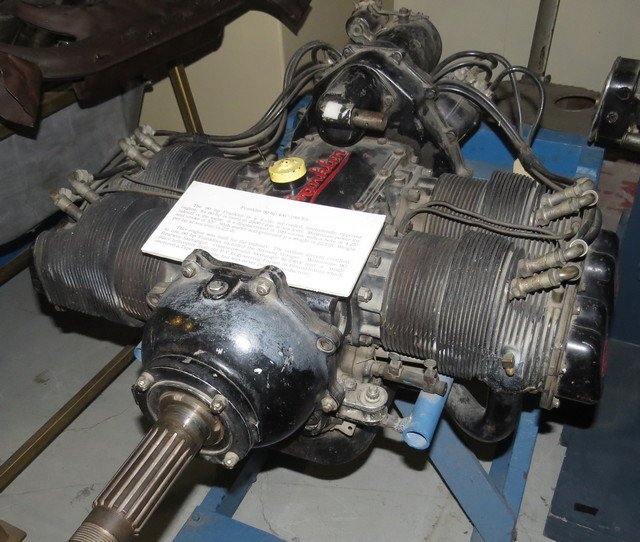
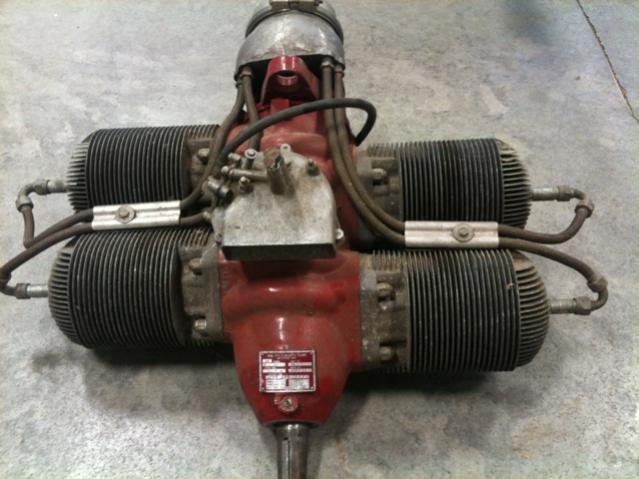
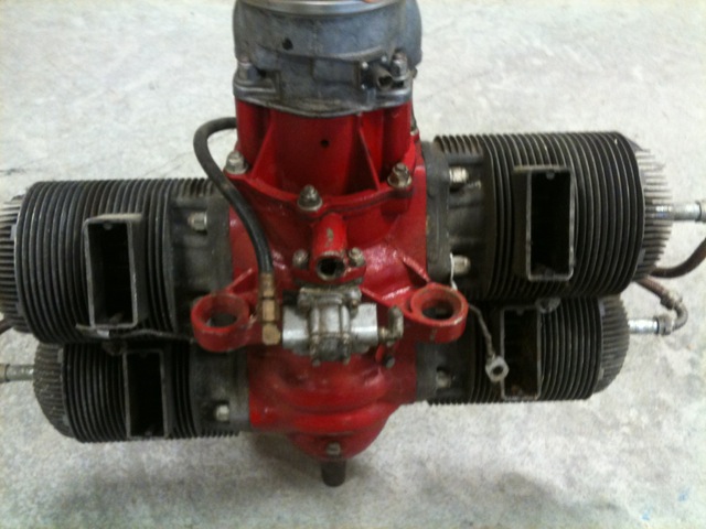
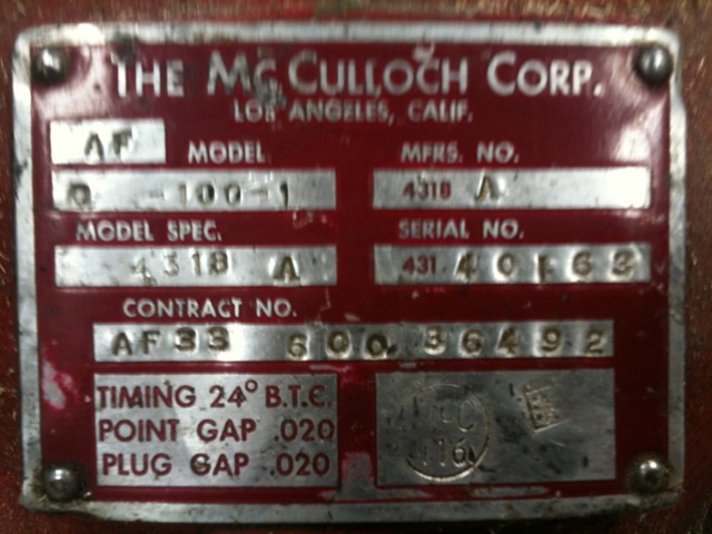
McCulloch Engine Model O-100
McCulloch Motors Corporation of Los Angeles, their first aircraft product apparently was the production from 1943, under US Government contracts, of Righter-designed two-stroke cycle engines for WWII target drones.
The Model 0-100-1 Engine is a four-cylinder, opposed-type, air-cooled engine which operates on the conventional two-cycle principle. It is designed primarily to furnish power for propulsion of radio-controlled pilotless aircraft for target or guided missile purposes.
Used in Radioplane OQ-19D
Three pictures from miniairboatassoc.com:
(Wikipedia) - McCulloch Motors Corporation
McCulloch 0-100-1
| First Run: | 1943? | |
|---|---|---|
| Number Built: | ≈70,000+ | |
| Type: | 4 cylinder two-stroke horizontally opposed engine | |
| Bore: | 3.1875 in | |
| Stroke: | 3.125 in | |
| Displacement: | 99.7 cu in | |
| Length: | 26 in | |
| Width: | 27 in | |
| Dry Weight: | 83 lbs | |
| Power: | 72 hp at 4,100 rpm | |
| Compression Ratio: | 8:1 | |
| Fuel: | 115-145 octane | |
| Fuel mixture: | Ten to one | |
1947 Fairchild J-44-R-20
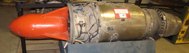
Turbojet aircraft engine
The Fairchild Engine Division (previously the Ranger Aircraft Engine Division of the Fairchild Engine & Aircraft Corporation) began development of the J44 in 1947. It was used in target drones, missiles, and as jet boosters on several aircraft types.
ASM 92-21-2
Fairchild J-44
| First Run: | 1947 | |
|---|---|---|
| Number Built: | ||
| Type: | turbojet | |
| Length: | 88.5 in | 2,250 mm |
| Diameter: | 22.35 in | 568 mm |
| Dry Weight: | 345 lbs | 156 kg |
| Components | ||
| Compressor: | Single stage centrifugal flow compressor | |
| Combustors: | Annular combuster | |
| Turbine: | Single stage turbine | |
| Fuel type: | JP-4 | |
| Oil system: | Oil-mist total loss | |
| Performance | ||
| Maximum thrust: | 1,000 lbf | 4.45 kN |
| Specific fuel consumption: | 0.94 lb/lbf/hr | 95.82 kg/kN/hr |
| Thrust-to-weight ratio: | 2.9 | |