Speed And Drift Indicator
books.google.com - Popular Aviaion April 1929 Page 31 Aerial Navigation for the Novice
Now for speed and drift indicators. Fig. 1 shows a well known American type, and Fig. 2 a popular British make of indicator. At present the only practical way of obtaining "drift" and ground speed, is by observation of objects on the ground, and both the above instruments are based on this principle.
The instrument shown in Fig. 1 may be mounted anywhere provided an unobstructed view downwards is obtainable (vertical if possible, but at an angle if more convenient). It is sometimes desirable to have two or more positions for mounting this instrument, so that it may be transferred quickly from one to the other, according to the direction or the drift and the convenience of the navigator. To obtain the drift angle, first make fast the support for the eyepiece in a convenient position. It is not necessary that the eyepiece be directly over the wire. The navigator then sights through the eyepiece at the drift wire and the ground below. The vane is now rotated so that the objects on the ground (or in the sea) appear to travel along the drift wire; i. e., the drift wire is placed in line with the course being made good over the ground. The drift angle, or angle between the heading of the plane and the course being made good can now be read from the scale.
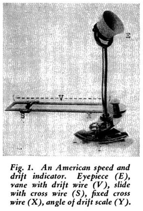
To obtain the ground speed, the vane is allowed to remain in the position corresponding to the drift angle, and the slide is moved along the vane until the cross wire is at the figure corresponding to the altitude of the plane above the ground which it is flying over. Looking through the eyepiece, the distance seen on the ground is that marked on the side of the vane—either one-tenth mile, four-tenths mile, or one mile. The scale that reads "One mile for altitude in thousand feet" can also be used for "One-tenth mile for altitude in hundred feet."
With a watch the time of passage of an object from one wire to the other is noted, and reference to a table which is furnished with the instrument gives the corresponding speed in miles per hour. This instrument may be calibrated for nautical miles or kilometers, instead of statute miles; and the conversion table furnished may also be used for any units of distance.
Fig. 2 represents a British product which is known as "Wind Gauge Bearing Plate Mark II" and which utilizes the air speed as given by the air speed indicator in a very simple manner to ascertain (a) the force and direction of the wind, and (b) the true course and speed of the machine with regard to the earth, ready for plotting on map. The instrument consists of a main casting on which is mounted a rotative divided circle and celluloid disc forming the actual bearing plate. Arrangements are provided for installing instrument in various convenient positions, but always parallel to the longitudinal axis of the plane.
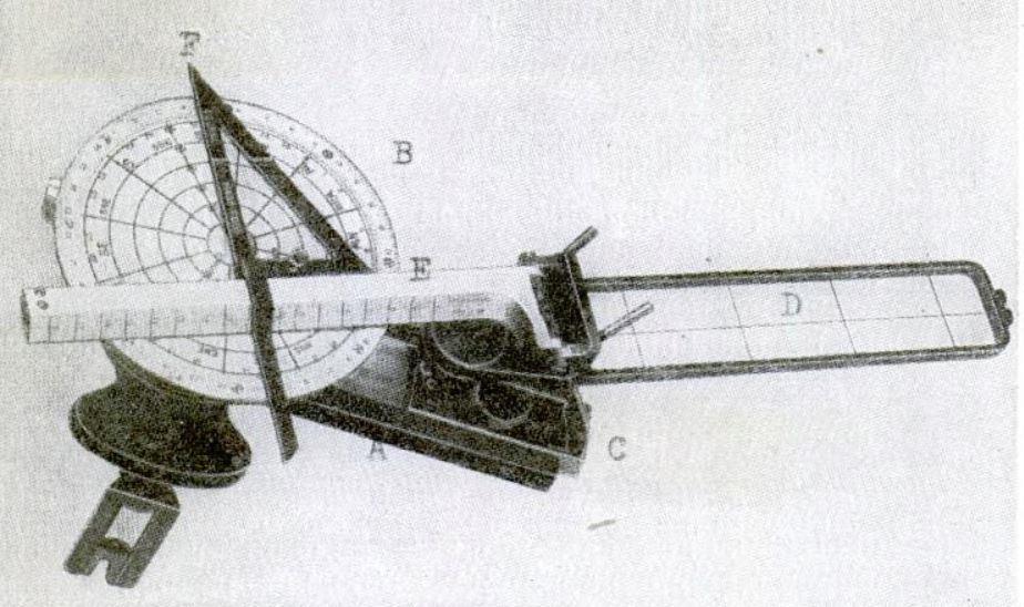
A slide that works in the fore and aft line of the plane is provided; mounted on the slide are the drift frame with its wire and the ruling bar, the first forward, the latter aft, both being rigidly connected together and rotating in azimuth about a pivot secured to the slide.
The ruling bar is hinged to allow for its movement in a vertical plane and the whole is so arranged that when folded down the ruling bar rests on the bearing plate. On the ruling bar is engraved the air speed and ground speed scale, the reacting marks being the center of the bearing plate (marked with a dot) and the wind point respectively. A brass square is arranged to slide along the ruling bar, the left side of which is hinged to allow folding, and this slide is engraved "Course made good."
Both the slide and the azimuth motion of the ruling bar and drift frame are fitted with clamping gear, while the bearing plate is self-clamping, being only free when pressed down. Among the advantages claimed for this instrument by the manufacturers is that it can be readily operated by heavily gloved hands.
It must be borne in mind that the best of drift and ground speed instruments are not perfect in their present stage. It is worth noting, that new ones are, however, being invented (on paper at any rate), and the navigator is in danger of being deluged with gimcrack methods, tables, diagrams and brazen instruments. Some of these are wonderful.
Heretofore we have been concerned entirely with dead reckoning, i. e., estimating a plane's position by course and speed from a well determined position. The next step is pilotage, i. e., determining a plane's position by reference to fixed objects on the earth, radio beacons, etc.
I recall reading somewhere in connection with aerial navigation a passage substantially like the following: "In practice, an experienced navigator would not actually observe with instruments the bearings and distances of objects in sight, as his judgment of position would suffice for ordinary needs." My own experience is, that it is extremely difficult to judge distances when aloft, and that on a flight of any length frequent fixes, and not mere judgments of position are essential. We must get back to Bowditch's definition which states the case about as well as it can be put: "the science generally termed navigation, which affords the knowledge necessary to enable the mariner (airman) to determine the position of his vessel at any time."
With the aid of an efficient magnetic compass and a drift and speed indicator, we are able to make a near approximation to ground speed; but the problem of fixing a position even under the best of weather conditions, still remains. A recent fix is invaluable if fog should come down suddenly, or if heavy rain or snow are encountered; and is of equal value whether the pilot under these conditions wishes to make a landing or desires to carry on. The failure of some of the British Navy planes to make their objective during one of the first raids on German territory (Dec. 26th, 1914), was mainly due to absence of fixes just previous to encountering fog.
The aircraft of tomorrow on long flights will provide the navigator with his own cockpit, and instruments, and a continuous chain of fixes will be the ordinary routine. Since this is not the case, a brief resume of marine methods, most of which can be adapted to aerial needs, may prove of value.
A knowledge of the use of (a) bearings and (b) angles is in any case bound to be useful. The first group is to a large extent dependent on the accuracy of the estimate of ground speed and drift, and on the correctness of the compass; the second group is independent of these factors. It is not so very long ago in marine circles that what is known as "cross bearings" were a staple diet. This scheme which is worthy of our old friend Hammurabi, consists of the taking of two bearings without any particular regard to the angle. I do not propose to confuse the novice with a description of...